
Page 20 - BASIC CONCEPTUAL OF THERMOFLUID
P. 20
CHAPTER 2: FLUID APPLICATION
Example 2.2
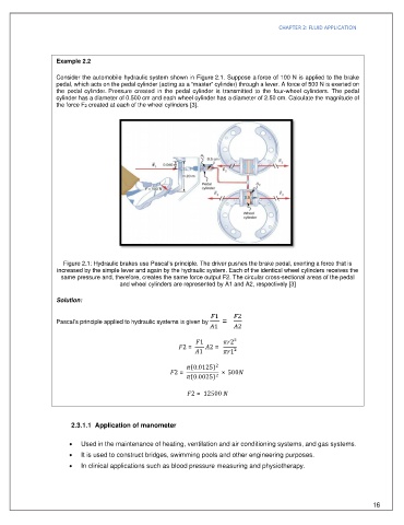
Consider the automobile hydraulic system shown in Figure 2.1. Suppose a force of 100 N is applied to the brake
pedal, which acts on the pedal cylinder (acting as a “master” cylinder) through a lever. A force of 500 N is exerted on
the pedal cylinder. Pressure created in the pedal cylinder is transmitted to the four-wheel cylinders. The pedal
cylinder has a diameter of 0.500 cm and each wheel cylinder has a diameter of 2.50 cm. Calculate the magnitude of
the force F2 created at each of the wheel cylinders [3].
Figure 2.1: Hydraulic brakes use Pascal’s principle. The driver pushes the brake pedal, exerting a force that is
increased by the simple lever and again by the hydraulic system. Each of the identical wheel cylinders receives the
same pressure and, therefore, creates the same force output F2. The circular cross-sectional areas of the pedal
and wheel cylinders are represented by A1 and A2, respectively [3]
Solution:
Pascal’s principle applied to hydraulic systems is given by =
1 2²
2 = 2 =
1 1²
(0.0125)
2 = × 500
(0.0025)
2 = 12500
2.3.1.1 Application of manometer
· Used in the maintenance of heating, ventilation and air conditioning systems, and gas systems.
· It is used to construct bridges, swimming pools and other engineering purposes.
· In clinical applications such as blood pressure measuring and physiotherapy.
16