Page 33 - Template EBook Kita (A4 Document)
P. 33

TOPIC 3: ASTABLE MODE


                                      SCHEMATIC CIRCUIT


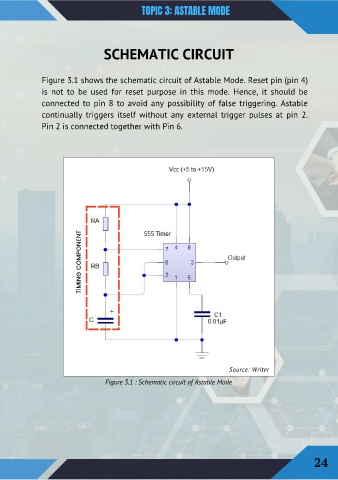
                Figure 3.1 shows the schematic circuit of Astable Mode. Reset pin (pin 4)
                is  not  to  be  used  for  reset  purpose  in  this  mode.  Hence,  it  should  be
                connected to pin 8 to avoid any possibility of false triggering. Astable

                continually  triggers  itself  without  any  external  trigger  pulses  at  pin  2.

                Pin 2 is connected together with Pin 6.


                             TIMING COMPONENT


                                                                                  Source: Writer

                                      Figure 3.1 : Schematic circuit of Astable Mode


                                                                                                                24
   28   29   30   31   32   33   34   35   36   37   38