
Page 34 - Template EBook Kita (A4 Document)
P. 34
TOPIC 3: ASTABLE MODE
OUTPUT WAVEFORM
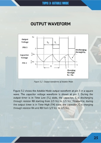
Figure 3.2 : Output waveforms of Astable Mode
Figure 3.2 shows the Astable Mode output waveform at pin 3 in a square
wave. The capacitor voltage waveform is shown at pin 2. During the
output timer is in Time Low (TL) state, the capacitor, C is discharging
through resistor RB starting from 2/3 Vcc to 1/3 Vcc. Meanwhile, during
the output timer is in Time High (TH) state, the capacitor, C is charging
through resistor RA and RB from 1/3 Vcc to 2/3 Vcc.
25