
Page 17 - Template EBook Kita (A4 Document)
P. 17
TOPIC 1: INTRODUCTION TO 555 TIMER
PIN ASSIGNMENTS
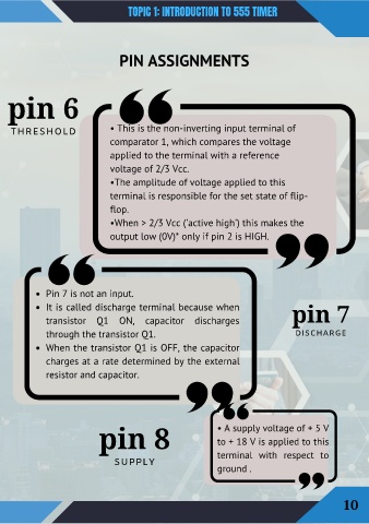
pin 6
THRESHOLD • This is the non-inverting input terminal of
comparator 1, which compares the voltage
applied to the terminal with a reference
voltage of 2/3 Vcc.
•The amplitude of voltage applied to this
terminal is responsible for the set state of flip-
flop.
•When > 2/3 Vcc ('active high') this makes the
output low (0V)* only if pin 2 is HIGH.
Pin 7 is not an input.
It is called discharge terminal because when pin 7
transistor Q1 ON, capacitor discharges
through the transistor Q1. DISCHARGE
When the transistor Q1 is OFF, the capacitor
charges at a rate determined by the external
resistor and capacitor.
pin 8 • A supply voltage of + 5 V
to + 18 V is applied to this
terminal with respect to
SUPPLY
ground .
10