Page 15 - Template EBook Kita (A4 Document)
P. 15

TOPIC 1: INTRODUCTION TO 555 TIMER


                                     PIN ASSIGNMENTS


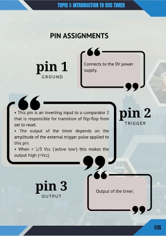
                           pin 1                             Connects to the 0V power

                                                             supply.

                               GROUND


           • This pin is an inverting input to a comparator 2                         pin 2

           that is responsible for transition of flip-flop from

           set to reset.                                                                  TRIGGER
           •  The  output  of  the  timer  depends  on  the

           amplitude of the external trigger pulse applied to

           this pin.
           •  When  <  1/3  Vcc  ('active  low')  this  makes  the

           output high (+Vcc).


                          pin 3


                               OUTPUT                                 Output of the timer.


                                                                                                                08
   10   11   12   13   14   15   16   17   18   19   20