
Page 20 - Template EBook Kita (A4 Document)
P. 20
TOPIC 1: INTRODUCTION TO 555 TIMER
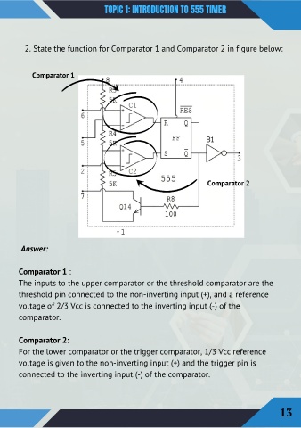
2. State the function for Comparator 1 and Comparator 2 in figure below:
Comparator 1
Comparator 2
Answer:
Comparator 1 :
The inputs to the upper comparator or the threshold comparator are the
threshold pin connected to the non-inverting input (+), and a reference
voltage of 2/3 Vcc is connected to the inverting input (-) of the
comparator.
Comparator 2:
For the lower comparator or the trigger comparator, 1/3 Vcc reference
voltage is given to the non-inverting input (+) and the trigger pin is
connected to the inverting input (-) of the comparator.
13