
Page 39 - ENGINEERING DRAWING
P. 39
32
CHAPTER 3 Orthographic Projection and Isometric
3.1 Introduction
All forms of engineering and technical work require that a two-dimensional surface
(paper) be used to communicate ideas and the physical description of a variety of shapes.
Projections have been divided into two basic categories which are pictorial and Multi
View. This simple division separates single view projections (oblique, perspective, and
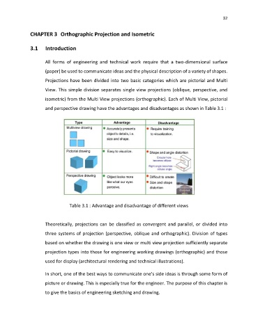
isometric) from the Multi View projections (orthographic). Each of Multi View, pictorial
and perspective drawing have the advantages and disadvantages as shown in Table 3.1 :
Table 3.1 : Advantage and disadvantage of different views
Theoretically, projections can be classified as convergent and parallel, or divided into
three systems of projection (perspective, oblique and orthographic). Division of types
based on whether the drawing is one view or multi view projection sufficiently separate
projection types into those for engineering working drawings (orthographic) and those
used for display (architectural rendering and technical illustrations).
In short, one of the best ways to communicate one’s side ideas is through some form of
picture or drawing. This is especially true for the engineer. The purpose of this chapter is
to give the basics of engineering sketching and drawing.