
Page 94 - ENGINEERING DRAWING
P. 94
87
5.4 Hatch Pattern
Hatch lines are thin lines and when they are laid out at a specific angle and spacing, a hatch
pattern is formed. A hatch pattern is always within a closed boundary. If there is a gap in a
section, hatching will not occur when using CAD systems. The spacing of hatch lines
should enhance readability. Depending on the size of the drawing, it may be between 1.5
mm (0.06 in) to 6 mm (0.25 in) in relatively small drawings. Likewise, the inclination of hatch
lines should be guided by clarity. The angle of inclination for hatch lines normally varies
o
o
o
o
o
o
o
between 15 and 75 . Popular angles are 15 , 30 , 45 , 60 , and 75 . The angle 45o is the
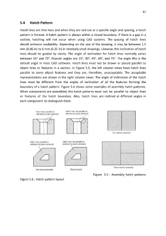
default angle in most CAD software. Hatch lines must not be drawn or placed parallel to
object lines or features in a section. In Figure 5.5, the left column views have hatch lines
parallel to some object features and they are, therefore, unacceptable. The acceptable
representations are shown in the right column views. The angle of inclination of the hatch
lines must be different from the angles of inclination of all the features forming the
boundary of a hatch pattern. Figure 5.6 shows some examples of assembly hatch patterns.
When components are assembled, the hatch patterns must not be parallel to object lines
or features of the hatch boundary. Also, hatch lines are inclined at different angles in
each component to distinguish them.
Figure 5.5 : Assembly hatch patterns
Figure 5.6 : Hatch pattern layout