Page 84 - basic control system
P. 84

TRANSIENT RESPONSE


                                             ANALYSIS


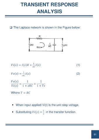
             ❑ The Laplace network is shown in the Figure below:


                                         1
                      =          +                                                           (1)


                             1
                      =                                                                      (2)


                                 1               1
                        =                 =
                            1 +              1 +     


              Where    =     


               ▪ When input applied Vi(t) is the unit step voltage.


                                                     1
               ▪ Substituting         =                 in the transfer function.


                                                                                                                  61
   79   80   81   82   83   84   85   86   87   88   89