Page 50 - PNEUMATIC SYSTEM INSTRUMENT
P. 50

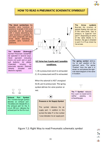
HOW TO READ A PNEUMATIC SCHEMATIC SYMBOLS?


            The  block  symbolises  the                                                  The     Arrow    symbols
            possible  valve  functions  or                                               illustrate  the  direction  of
            posit  ions. Example: A 5/2 valve                                            gasses flowing into and out
            schematic  will  be  illustrated                                             of  the  valve  ports.  Gas  is
            with  2  blocks  describing  two                                             pressure  is  supplied  from

            valve functions or positions. A                                              port P. Depending on which
            5/3  valve  schematic  will  show                                            of  the  valve  blocks  is  in

            three  blocks  describing  3
            possible  valve  functions  or                                               function, the gas is directed
            positions.                                                                   to port A or B as shown by
                                                                                         the arrows.


           The   Actuator   (Solenoid)

           Symbol Pneumatic valves can
           be  operated  in  several  ways.
           Hand     operated   (including
           levers  and  push  and  or  push                                           The  spring  symbol  defines
           pull   buttons);   Air   piloted   5/2 Valve has 5 ports and 2 possible    the  "at  rest"  position  of  the

           (Operated    remotely    by                  conditions.                   solenoid  valve.  The  spring
           pneumatic  signals);  Solenoid                                             "Pushes"  from  the  side  it  is
           (directly   actuated   with                                                drawn on and places the right-

           electronic signals)            1.) B is pressurized and A is exhausted.    side block diagram of the valve
                                          2.) A is pressurized and B is exhausted.    in function.


                                          When the solenoid is NOT energized
                                          the B, port is pressurized. The spring
                                          symbol defines the valve position at

                                          rest.
                                                                                     The  T  Symbol  indicates
                                                                                     that a port is closed and is
                                                                                     neither   passing    nor
          Exhaust    Port   Symbol                                                   exhausting gas.

          The inverted triangle symbol
          denotes  an  exhaust  port.          Pressure or Air Supply Symbol

          The letters EA indicate this is
          the  exhaust  port  for  the  A
          circuit. EB turn indicates the       This  symbol  indicates  the  air

          exhaust port for the B circuit.      supply  port.  In  addition  to  this
                                               symbol the letter P or the number
                                               1 also indicates the air supply port.


                      Figure 7.2: Right Way to read Pneumatic schematic symbol


                                                           33
   45   46   47   48   49   50   51   52   53   54   55