
Page 46 - PNEUMATIC SYSTEM INSTRUMENT
P. 46
DIRECTIONAL CONTROL VALVE SYMBOL
DEVELOPMENT
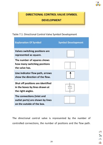
Table 7.1: Directional Control Valve Symbol Development
Explanation Of Symbol Symbol Development
Valves switching positions are
represented as square.
The number of squares shows
how many switching positions
the valve has.
Line indicator flow path, arrows
show the direction of the flow.
Shut off positions are identified
in the boxes by lines drawn at
the right angles.
The connections (Inlet and
outlet ports) are shown by lines
on the outside of the box.
The directional control valve is represented by the number of
controlled connections, the number of positions and the flow path.
29